Stairs in Revit can be a source of chaos and frustration.
It doesn’t have to be that way. This guide breaks down all the complex parts into easy to digest small bites. We promise that after reading this, everyone will be baffled by how great of a stair modeler you’ve become. Enjoy these tips.
1- UNDERSTAND ALL REVIT STAIRS DEFINITIONS
Before doing anything, you need to understand all Revit stairs definitions. Have a look a the visual legend below to make sure you get everything.

BASE AND TOP LEVELS: Stairs are based on selected levels that already exist in the project. You can add an offset on these levels if required.

DESIRED STAIR HEIGHT: Total distance between the base and the top of the stairs, including offsets.

DESIRED NUMBER OF RISERS: Automatically calculated by Revit, dividing Stair Height by Maximum Riser Height. You can change this number, which will modify the stair slope.

ACTUAL NUMBER OF RISERS: The number of risers you modeled so far.
MAXIMUM RISER HEIGHT: Riser height for your stair will never go above this value. This parameter is set on the stair type. Usually on par with code requirements.

ACTUAL RISER HEIGHT: This distance is automatically calculated by Revit, dividing the Stair Height by the Desired Number of Risers.

MINIMUM TREAD DEPTH: On the stair type, specify the minimum tread depth. When you start modeling your stair, you can go above this number, but not below.

ACTUAL TREAD DEPTH: By default, this value is equal to minimum tread depth set in the stair type. However, you can set a bigger value if you want more depth.

MINIMUM RUN WIDTH: Set on the stair type, you can specify the minimum run width. This does not include support (stringers).

ACTUAL RUN WIDTH: By default, this will be the same as the minimum run width. You can set a higher value than the minimum, but a lower value will result in a Warning.
2- SET MINIMUM AND MAXIMUM VALUES IN STAIR TYPE
Now that you understand what all these Revit stair definitions mean, time to set them up. Select the stair tool in the architecture tab. Then, click on Edit Type in the properties. Adjust Maximum Riser Height, Minimum Tread Depth, and Minimum Run Width. Usually, these values are set in order to satisfy code requirements. This will affect all stairs using this type.

3- SET BASE AND TOP LEVELS
Select your base and top levels. Set offsets. Desired Stair Height will be automatically calculated.

4- DRAW THE STAIR FROM BOTTOM TO TOP
You can now begin to draw your stair. There are many stair shapes options, for now let’s use the most common straight one. Click a first time to set the start point of your stair. Move your cursor to see the projected shape of your run, based on the tread depth you have set previously. Click again to complete the run.


When drawing a stair path, you start at the low point and end with the top of the stairs. If you did it backward, flip the stairs, by clicking the Flip button or clicking the arrow symbol.
5- HAVE A CLOSE LOOK AT OPTIONS BAR

When entering the stair creation mode, have a look at the option bar. You can change Location Line to decide if you want to draw the stairs based on the side or on the center of the run. You can also change the Actual Run Width to go above the minimum you specified previously.
6- USE 3D VIEWS AND SECTIONS
Using 3D views in addition to plan views and sections is a great way to build and understand stairs. Use Selection Box to isolate the stair in the 3D view if required. To create stairs from a 3D view, make sure the Workplane is set to a plan level, else you will receive a warning.
7- UNDERSTAND WHERE TO FIND ALL PARAMETERS
Finding all stairs parameters can be confusing. It’s because the stair type contains three sub-type of elements, where more parameters are located.

STAIR TYPE: Controls the dimension rules of your stairs, like riser height, tread depth and run width. Inside Stair Type, you will also find Run Type, Landing Type, and Support type.
To modify these types, either go to Stair Type or use TAB to individually select a run, landing or support. Then click Edit Type.
RUN TYPE: Inside this type, you can modify Tread Thickness, and set a Nosing Length
to your treads. You can also set Riser Thickness and decide if you want them slanted. Also, use this panel to set materials for tread and risers.
LANDING TYPE: By default, this will be the same as Run Type. Uncheck the box Same as Run to customize landing material, thickness, nosing, etc.
SUPPORT TYPE: Specify whether to use Carriage or Stringer style support. Also set support Material, Width, and Depth. See advanced tips for more information.
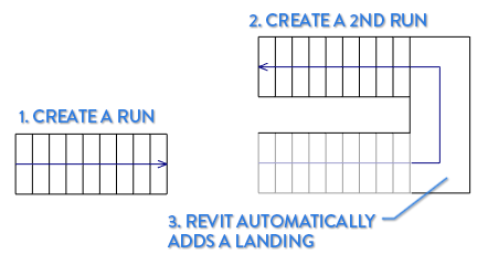
7- LANDINGS ARE AUTOMATIC BY DEFAULT
If you draw two stairs run next to each other, Revit will automatically add a landing to join the two. You can uncheck this feature when creating the stairs (see tip 2).
Landings at the top or at the bottom of the stairs are never automatic, they have to be created manually. Use the Landing Component and select Create Sketch button. Then draw the outline of the landing.

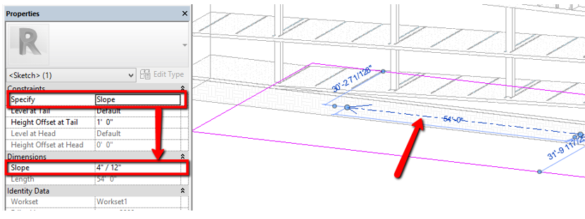
8- ADJUST “DESIRED NUMBER OF RISERS” TO CHANGE STAIR SLOPE

By default, Desired Number of Risers will be equal to the lowest number of risers you need to not go beyond Maximum Riser Height. However, you can specify more risers to get a softer stair slope. Don’t ever put fewer risers than the calculated minimum, else you will receive a warning!
9- ADJUST “ACTUAL TREAD DEPTH” FOR A LONGER RUN
Instead of adding risers, you can also put a bigger value to Actual Tread Depth for a softer stair slope. Changing this value will make the run longer. Again, don’t put a number below the Minimum Tread Depth, else you will receive a warning. Warnings are annoying and mean that you are not following your own rules.
10- ADJUST “BEGIN WITH RISER” AND “END WITH RISER”
In the image below, RUN #1 has the default settings: it begins and ends with a riser. However, we changed the settings for RUN #2, which begins and ends with a tread instead of a riser. You can change this option by clicking on a run and checking/unchecking the parameters.

11- SELECT RAILING TYPE WHILE CREATING STAIRS

While creating stairs, railings will automatically be added to your stair. The default type will be the last one selected. To change it, click the railing button and select another type, or select None for a stair without railing.
12- SELECT CARRIAGE OR STRINGER SUPPORT TYPE
A Carriage Support is underneath the stair, following the shape of treads and risers. This is a type usually used for a wooden residential stair type. A Stringer Support will be separate from the stairs, usually on par with metallic stairs construction type. These settings are found in Stair Type.

Source: https://revitpure.com/